Building a face that can perform an expression.
Outcome: a physical mechanism that reads a performer’s facial movement and translates it into real-time mechanical motion.
Rap performance is physical. Expression changes how a line feels.
I wanted to go beyond identifying a performer on screen. Could a machine read expression as motion—and then reproduce part of that presence with an object I designed and built?
“What happens when computer vision leaves the screen and becomes a mechanism?”The engineering question
Close the loop between seeing and moving.
The system needed to locate facial movement, convert that movement into controllable values, map those values to actuators, and produce a visible response without breaking the mechanism.
Five linked subsystems turn a face into motion.
Showing the complete system first makes the role of each technical tool immediately understandable.
Observe
A camera captures the performer’s face and changing expression.
Live videoTrack
Facial landmarks convert visible features into measurable positions.
Computer visionMap
Selected distances or angles become control values for the mechanism.
Motion dataActuate
Servos pull or release mechanical elements to create movement.
Physical controlIterate
Observed mismatch or failure informs the next CAD and control revision.
Prototype loopCAD proves design skill. The built face proves follow-through.
The motion trace connects the software and hardware: it makes the control signal visible between facial tracking and physical actuation.
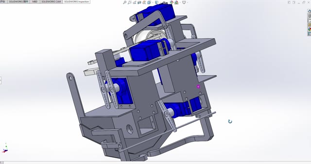
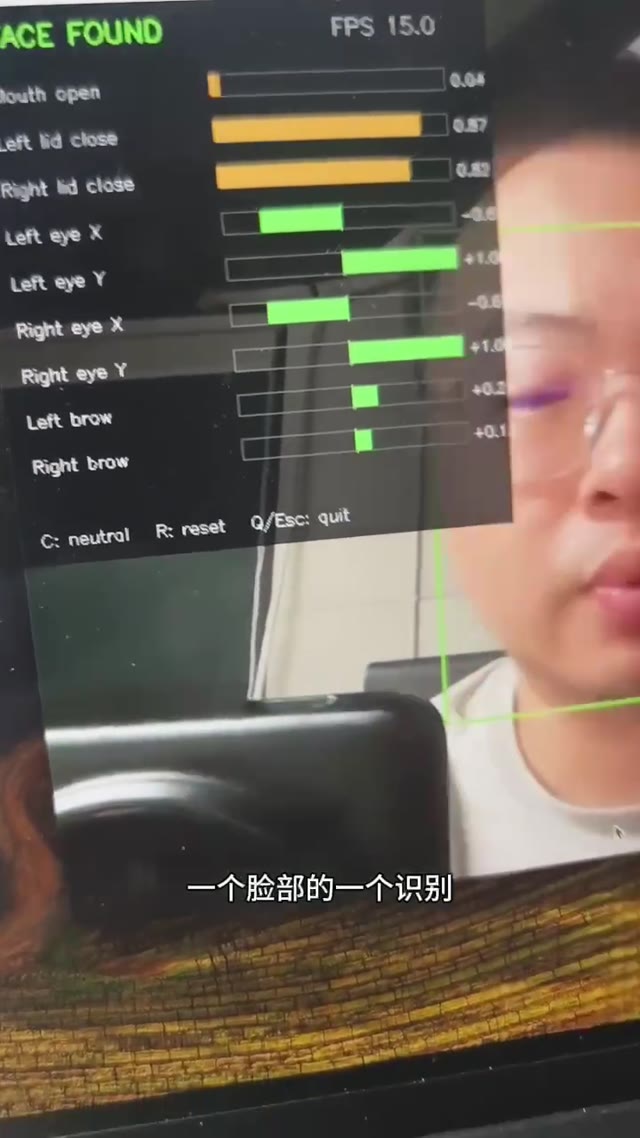
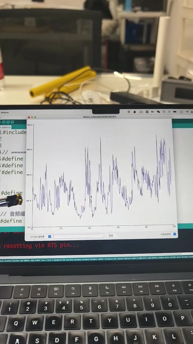
Every tool occupies a specific place in the system.
Define geometry, fit, range of motion, and assembly before fabrication.
Move quickly from a digital mechanism to testable physical parts.
Reduce an expressive face to positions, distances, and angles the controller can use.
Translate control values into repeatable pulling and releasing motion.
Design the face as a system, not a sculpture.
Geometry had to serve motion paths, actuator placement, assembly, and repair.
Choose a reduced set of expressions.
A useful prototype maps a few visible motions reliably before attempting a fully human face.
Debug across disciplines.
A bad output may come from tracking noise, control mapping, mechanical friction, or structural failure; each requires a different test.
Measure expression instead of relying only on “it moves.”
These are proposed next steps, pending Tony’s confirmation.
Calibrate
Measure latency, actuator range, and repeatability for each tracked facial movement.
Add resolution
Increase degrees of freedom only where they produce a clearly more expressive result.
Refine the object
Improve cable routing, safety, and the enclosure so the mechanism can be demonstrated repeatedly.